![[SoundStage!]](../sslogo3.gif) Feature Article Feature Article |
| Pete Goudreau is a senior design engineer with 20 years experience
in e-beam lith; ion- and electron-beam systems and source design; power-supply design;
analog, digital, and RF design. He admits freely that he's "completely obsessed with
audio," and this article, the first in his quarterly series on sound and engineering
topics, should prove it. Expect to see articles on topics from planar speakers to passive
and active preamps -- with stops in between. September 1998 Pete's Place by Pete Goudreau I can't believe it -- I'm actually discussing cables. Not being one to think much of tweaky things, I had once relegated cables to that intellectual dumpster where green ink, demagnetizers, and little wooden pucks reside under the assumption that audible differences in cables would be far too slight to be noticeable in my system. As it turns out, that assumption was wrong. Late last year, former SoundStage! writer Mike Fenech came to visit and brought his own cables for a comparative test in my system. To my surprise, the cables did sound distinctly different from my own, and this little incident set me to thinking about the role of signal integrity and grounding in audio systems. Turns out that the commonly held belief that only the differential-mode lumped parameters of cables (that's R, L, and C to you and me) make any difference to a cable's sonic contribution isn't all there is to consider in this application. There are the common-mode parameters of the system configuration to consider as well. These parameters, often misunderstood or ignored, play as an important, if not more important, a role than the more easily understood differential parameters. Pro audio users and designers know well that signals carried by unbalanced cables are noisier at the receive end than they are at the transmit end; it's just a simple matter of Ohm's Law (v=iZ). Figures 1a and 1b below depict two typical ways in which signal, power, and ground become interconnected between two pieces of equipment when linked together with an unbalanced cable. The ways in which a system configuration defines interchassis potentials and thus the noise added to the signals as a function of the common-mode parameters of the interconnects and power cords aren't simple to understand, but a discussion follows in the hopes that you might gain a clearer understanding of what the average audiophile, and a good number of engineers, often considers to be black magic. Those wishing to avoid technobabble overload might want to jump ahead to the end and avoid the annoying textbook stuff that follows. Interchassis potentials Depending on the design of the equipment in question, the signal return of the connectors, which is the shell on an RCA, may be tied directly to chassis or it may be floating with respect to the chassis, as shown in Figures 1a and 1b below. Note that in the latter instance (Figure 1a) there is an impedance composed of a parallel R and C between signal return and chassis whereas in the former (Figure 1b) there is a similar impedance between chassis and neutral. It should be clear then that every signal return has an internal path to ground regardless of the detailed design of the equipment. Unless one of the pieces of equipment is battery powered, there is then a loop formed by linking the two chassis together with an unbalanced interconnect as shown in Figures 1a and 1b by the paths labeled noise current loop. Note that in Figure 1a, this loop does not contain any wiring beyond the local distribution center, whereas in Figure 1b the internal building wiring all the way back to the building load center is part of the loop.
The noise current in this loop flows in response to an interchassis potential generated by the interaction of each chassis' differing line and neutral leakage currents with the common-mode impedance of their respective power cords. The current drawn by each power supply, through its interaction with the differential-mode impedance of its power cord and AC mains wiring, can introduce an additional interchassis potential in certain special cases. RF fields, intercepted by the loop, also generate a potential around the loop that induces an additional noise current. Causes The following discussion will center on the causes of interchassis potential, first through consideration of leakage currents and second through power-supply interactions, and the techniques by which it may be minimized. Other sources of noise currents, nonlinearities in active stages, their impact on effective noise-floor characteristics, and the unbalanced interconnect's role in converting noise current to a noise voltage are discussed in relation to interconnect design. The "Y" capacitors in Figures 1a and 1b, labeled Cys and Cyd, generate a leakage current that flows in the power cord's ground and neutral wires. These capacitances may or may not exist as actual parts in the equipment as the winding method of the power transformer and the power wiring in the equipment forms parasitics that would appear in the schematic in exactly the same manner. These caps are also part of any input EMI filter and add with the parasitics of the unit's construction. Designers, however, often eliminate the cap between line and chassis, as in Figure 1b, when there is no EMI filter or three-wire cord installed, or in equipment where an internal high gain stage might generate too much noise and hum. A resistor is sometimes added between neutral and chassis to form a local reference for the signal returns that are then typically connected to chassis. This added resistor, however, is occasionally left out of the design under the assumption that the destination equipment, a preamp for example, will provide the reference to ground, as in most consumer equipment. Safety is still guaranteed, however, because the open circuit potential, while high, is not dangerous owing to the high impedance of the "Y" caps that limits ground-fault current to a safe level. Power-supply currents, as drawn from the wall, can also create a chassis potential above ground, but only if the two "Y" caps are not of equal value, as shown in Figure 1b. A simple network analysis shows this effect to be true while also showing that if the two caps are equal, as shown in Figure 1a, the symmetry in the network causes cancellation of any chassis potential arising from power-supply input currents flowing through the power feed's differential-mode impedance. This differential impedance, as seen by each piece of equipment, is a series combination of its power cord and associated building-wiring impedances through which the power supply's input current circulates. The total potential induced on the chassis is then a function of the total current flowing in the building wiring between the building's load center and the local system power-distribution center (read power strip or wall outlet, etc.), and all the way back to the power company's generator terminals for that matter. This is true for the simple reason that all equipment sharing this path also generates circulating currents that add with those of the piece of equipment in question. This makes it essentially impossible for the power cord itself to make a significant reduction in the chassis potential in this instance as its impedance is nearly always smaller than the driving-point impedance presented by the AC mains. This also indicates that the AC line can only be as quiet as the noisiest source sharing the feedline. It should be noted, however, that distributed parasitics and distribution transformers in the power-delivery grid effectively act as filters that make distant noise sources less important than local ones. While it's possible for some line conditioners to minimize this added differential-mode noise caused by other equipment sharing the line, it's not possible to reduce significantly the driving-point impedance of the AC mains at frequencies near the line frequency without supplanting the mains themselves with a new generator source. An approximation of this technique is occasionally employed at studios through the use of a motor-generator set. A sufficiently large flywheel between the motor and the generator (an alternator actually) effectively lowers the impedance of the line while simultaneously providing filtering of noise. Some line conditioners available to the consumer attempt to attain the same effect, with varying degrees of success, generally through the use of shunting capacitance or by actively regulating the output voltage. While many conditioners contain EMI filters, these act only to reduce differential-mode, as well as common-mode, noise yet actually slightly raise the effective driving point impedance at low frequencies as the differential-mode filter components add, however slightly, to those of the AC line. As an aside, note that the topology of the power supply can have a strong effect on the bandwidth of the induced chassis potential only in the case where the chassis to AC mains bypass is asymmetrical. For example, tube rectifiers with choke input filters generate a more sinusoidal input current waveform, whereas solid-state rectifiers with capacitor input filters typically generate a pulsing input current waveform. This pulsing current, while inherently wider in bandwidth than the approximately sinusoidal current in the first example, will then exhibit a chassis potential tilted upward with frequency, due to the inductance of the AC feedline. In the special case where the chassis-to-AC-mains bypass is asymmetrical and the local power-distribution center presents a lower driving-point impedance at high frequencies than that of a given power cord, and where the equipment exhibits a wideband power-supply-input-current waveform, it may be possible to reduce somewhat the chassis potential through the use of alternate winding geometries in the power cord, such as a StarQuad arrangement. Bear in mind, however, that it is only possible to reduce the resultant chassis potential above ground by the selection of a power cord in this particular instance, but it cannot be used to eliminate it entirely. If the power-supply design is such that it does not generate a wideband current waveform, then it's unlikely that a special power cord can have much of an effect on chassis potential through its interaction with the power-supply input current. Balanced power Balanced power converters are a relatively new type of power conditioner that have come on the market in recent years and are enjoying some success in recording studios. Their use can virtually eliminate leakage and power-supply-input-current-induced chassis potentials. It does so by providing a source of power where the neutral terminal is no longer connected to ground, as it is in all unbalanced AC power installations, but to a 60V rms source which is 180 degrees out of phase with the 60Vrms source connected to the line terminal. This is accomplished with a transformer that has a center-tapped secondary exhibiting 120V rms from end to end. The center tap is connected to ground and GFCI (ground fault circuit interrupt) duplex outlets distribute the balanced power, provided by the secondary side of the transformer, to the connected equipment. The beauty of this arrangement is that if the "Y" caps in the equipment powered by this method are equal valued, their open-circuit center-point voltage is zero. Since this center point is connected to the chassis of the equipment, when that chassis is connected back to the ground at the center tap of the transformer, there is no potential to force current to flow. This means that all chassis connected to this source of power can have no potential difference among them, and thus there is no noise current flowing in the noise-current loops shown in Figure 1. Pretty spiffy if you ask me. Better yet is the simple fact that since the effective use of a balanced AC power converter mandates the use of equipment with equal-valued "Y" caps, the chassis potential then cannot be dependent on the power-supply currents drawn by the equipment. Remember that if the "Y" caps are symmetric in value, the chassis potential induced by power-supply currents interacting with the differential-mode impedance of the power feed is zero due to cancellation in the network. In reality, since the symmetry isn't exact, there is some residual chassis potential, but it is far smaller than it would be otherwise. This is the really killer effect of this method of power conditioning as its use not only eliminates sensitivity to the driving-point impedance of the AC mains, the topology of the power supplies, and the differential impedance of the power cords, etc., it inherently eliminates the interchassis potential that would otherwise arise when using standard unbalanced power with symmetric "Y"-cap equipment. It's the best of both worlds. Unfortunately, it isn't a simple matter to achieve this configuration in the real world unless the equipment designer has been careful to closely match the "Y"-cap values, including the parasitics. An Equi=Tech balanced power converter is on the list for installation in my system sometime in the future, and this will require some modification of equipment for its effective use. I'll report on its effect on sonics as well as its impact on unbalanced interconnect sensitivity at a later date. When standard, unbalanced power is used to power a system, however, a voltmeter can be used to reduce chassis potentials due to asymmetrical leakage currents by allowing the user to optimally orient the power-cord polarity. This is actually a useful test in that if the system noise floor seems to drop in response to power-cord polarity changes, the two "Y" caps are then usually not equal in value and often different between on and off states of the equipment to boot, making it likely unsuitable for use on balanced power. However, if the equipment has a non-medical-rated EMI filter or discrete "Y" caps of equal value, this technique will have virtually no effect on the noise floor and is therefore likely to be suited for use with balanced power. Unfortunately, orienting the polarity of the AC power plug is generally the only available method to the audiophile for reduction of interchassis potential when balanced power is not an option. Also, given that several sources may be connected to a preamp that may or may not bridge some or all of the input and output signal returns, the situation is decidedly more complex and even more difficult to solve or at least ameliorate in most installations. I'd bet audiophilia nervosa is not an uncommon response to some situations, especially when you throw in a connection to the cable-TV feed. Loop antennae, skin depths, and shields As if all this weren't complicated enough, every unbalanced interconnection between AC-powered pieces of equipment forms a loop antenna. Any other loop formed by any closed path along any pair of interconnects, equipment inputs or outputs, and power cords is also a loop antenna. The RF potential induced around any given loop antenna due to flux linkage causes an RF current to flow that adds to the noise current generated by interchassis potentials. But, the effect of skin depth is supposed to make coaxial cables immune to this problem, right? Well, sort of. While it is true that as frequency increases, the depth into the shield that the current flows decreases until essentially none of this RF noise current is flowing on the inside of the shield thus making the cable self shielding above a frequency defined by the material and construction of the shield itself. Unfortunately, some of this RF current will "leak" across the shield and induce an added noise voltage as part of the signal. This effect, known as transfer impedance in signal integrity parlance, is not only real but calculable and measurable and is of a different nature than that of the noise-current loop's effect. For calculation purposes, the transfer impedance when multiplied by the RF noise current flowing in the shield yields the noise voltage added to the signal. Thus the transfer impedance should be as low as possible over as wide a frequency range as possible. Transfer impedance is fundamentally a measurement of the external field that gets coupled across the boundary of the shield into the signal path itself. The physical properties and geometric configuration of the shield controls the magnitude of this effect. The difference is more obvious though at high frequencies (>1MHz to 10MHz) where the shield's mutual inductance becomes the dominant source of signal coupling. Interestingly, the transfer impedance rises with frequency above this point for virtually all shield constructions with the exception of a solid-copper shield such as that found in the JPS Labs Superconductor interconnect. As an example, spiral and folded aluminum foil shields have a rather high transfer impedance in comparison to nearly all other types. A braided copper shield is better and can be optimized through proper selection of strand diameter, grouping, optical coverage, and crossover angle, as well as the material properties themselves. Even when optimized, though, the transfer impedance reaches a minimum in the 1MHz to 10MHz region and climbs inductively beyond this, not to mention that it is significantly increased when the cable is formed to a radius, etc. Concentric braided shields perform slightly better, but the very small parasitics formed by the radial and longitudinal gaps inherent in their construction results in a severe ripple in the transfer-impedance curve with minimums tangent to the ideal inductive response. A solid copper shield on the other hand drops in magnitude through the 1MHz to 10MHz region, exhibits no minimum, and no subsequent inductive rise below several hundred megahertz. Thus the transfer impedance of a solid copper shield can be as much as 20 to 30dB lower than that of an optimized braided copper shield at 10MHz, and as much as 100dB lower at 50MHz . At lower frequencies, though, it is possible for the braid to have a lower transfer impedance than a solid copper shield unless the solid shield is made thick enough to provide an equivalent bulk resistance as is done in the Superconductor interconnect. Consider also in this context that the clock frequencies in transports, CD players, and outboard DACs are at either 16.9344MHz or 11.2896MHz, for 44.1ksps data, and that the clocks are generated with CMOS logic having rise times in the 2ns to 7ns range, and it is easy to see that the spectral content extends well beyond 100MHz since the first break in the fourier series for a trapezoidal waveform is at 1/pi*tr. Additionally, radiation efficiency of E field emissions rises at 20dB/decade and at 40dB/decade for H field emissions, making the near-field coupling of sources at these frequencies surprisingly strong since the near field for 100MHz extends easily to a few feet in space from the radiator. When you consider the fact that few pieces of equipment are designed to minimize their near-field emissions, it isn't too surprising that EMI pickup from digital audio equipment can easily find its way into every other piece of equipment in the system purely from radiative coupling effects. The JPS Labs Superconductors
You see, there's no such thing as a perfectly linear amplifier, or resistor for that matter. At some frequency or amplitude, nonlinearity exists at a magnitude that makes for some interesting effects. A nonlinear element in the signal path is going to create signals where there were none before. This isn't to say that something is created out of nothing, only that the signal energy is redistributed to the "new" signals, in passive nonlinearities anyway, to be more precise. The upshot of this technobabble is that no matter how clean the signal is when it comes into a piece of equipment, it can't be as clean coming out. One of the more germane aspects of nonlinearities is that if there are two perfect sine waves at two different frequencies going in, there will be sine waves at the sum and difference of their two frequencies coming out in addition to other distortion products. This is known as intermodulation. If these two frequencies going in are high-frequency noise, and that high-frequency noise is at frequencies where the internal circuitry is nonlinear, their distortion products end up in the audio band even if they weren't there to begin with. This is but one example of spectral contamination; ultrasonic and RF energy that finds its way into the circuitry can also cause other problems such as offsets, intrastage overloads, demodulation products, noise modulation, etc. The entire range of nonlinearity-related error is referred to as spectral contamination and is measurable through known techniques. RF and cables Well, what does all this power-line and RF stuff have to do with cables? Good question, and here's the answer -- about time too. Given the simple fact that an unbalanced cable linking two ground referenced pieces of equipment forms a loop and that since there must exist a potential difference around the loop due to chassis leakage and possibly power-supply currents, as well as intercepted RF flux, a noise current then flows. The return impedance (the common-mode impedance) of the interconnect converts this noise current to a noise voltage, at low frequencies, that adds to the signal voltage at the destination equipment, and the transfer impedance of the cable allows some of the induced RF current to superimpose a frequency dependent RF noise voltage on the signal. Spectral contamination will convert the higher-frequency components of this noise voltage to inband distortion products while the lower-frequency power-supply-related components will simply be amplified as inband components. Thus the common-mode and transfer-impedance characteristics of an unbalanced interconnect can directly affect the noise floor of the signal as processed by the destination equipment. Note that these two impedances are but two sides of the same coin, rather than two completely unrelated parameters, and the overall effect is bit easier to understand. Now, again, the observant reader is probably asking how this RF noise can get into the circuit in the first place. Isn't that what filters and stuff like that are for? Sure, you bet -- shame it's rarely done correctly though. Just because the schematic says there's a filter there doesn't mean that it works like one over the range of frequencies where noise is likely is get into the system due to chassis design and other EMC (electromagnetic compliance) considerations. Component parasitics that alter the filter response at high frequencies, radiative coupling across the filter, etc., usually defeat the best laid plans of the designer. In reality, all equipment exhibits, to some degree, conducted and radiated susceptibility to EMI/RFI. Conducted susceptibility is the lack of the ability of the input-stage-cable termination and filter design to adequately reject or filter out signals that might result in abnormal operation of the signal-processing circuitry. The actual design of the signal-processing circuitry itself is often important in this regard as well -- e.g., suppressed high-frequency gain in the first stage, elimination of miller integrator compensation stages, the use of folded cascode gain stages, careful shielding between stages, board-layout techniques that suppress common-mode signal flow through differential-mode signal paths, etc. Unfortunately, all of these are under the control of the equipment designer and cannot be addressed by the choice of interconnect. Radiated susceptibility is the lack of the ability of the enclosure and the input- and output-connector-return bypasses to shunt these high-frequency noise currents, riding on the outside of the shield, away from the signal-processing circuits located inside the chassis. The noise voltage induced by these currents is usually expressed as the transfer impedance of the cable termination and is typically added with the cable's transfer impedance in order to express the overall transfer impedance of the signal path. Note that the cable termination's transfer impedance is controlled only by the design of the equipment and cannot be reduced through reduction of the cable's transfer impedance. With the advent of digital equipment, this problem can be many times worse than it ever was with phono equipment, concerning local generation of EMI as detailed earlier, as opposed to the problem of designing and packaging a very high-gain-stage amplifier to reject low-level ambient RFI. In other words, today's home listening environment is not as benign as it once was, so it should come as little surprise that an unbalanced interconnect can sound different on different equipment and in different systems. Thus it behooves the user to choose an interconnect that provides as much immunity to EMI/RFI as possible in order to minimize its impact on equipment of unknown design quality. Is it audible? OK, so your equipment is impeccably designed for RFI rejection (it says so right here in the fine print of your bank balance) and the only noise of any concern is then that due to interchassis potential. The question then becomes whether or not this whole mess is even audible in the first place. And therein hangs a tale. I, for one, never considered this much of a problem as it's just so obvious that the noise must be so small that it can't possibly be heard in a normal listening environment at normal listening levels, right? Well, not so fast, it turns out life just isn't this simple after all (did he say simple?!). There's this little matter of common-mode resonances in the interconnection that just didn't get mentioned in too much detail above but the reader who is an electrical engineer will likely have clued into the fact that the loops discussed above are a series and parallel combinations of R, L, and C and that means resonances where the loss in the loop (the R) controls the Q of those resonances. Figure 1a shows a configuration that is not uncommon with a digital source. The Noise Current Loop drawn in the picture is the mesh to solve for the noise voltage that appears across the return path of the interconnect as a function of the interchassis potential. The solution of this mesh indicates that either Rcs or Rcd, or both depending on relative values, controls the Q of the resultant voltage divider with smaller values contributing to a lower Q. Note that in Figure 1b, the loop is a different topology but its solution is effectively identical. This indicates that lifting the earth of the power cord might make an audible difference but it can't eliminate the problem entirely. At high frequencies though, the loop can be viewed as a simple inductive voltage divider. This means that the ultimate rejection of the noise potential driving the loop is a direct function of the ratio of the common-mode impedances of the interconnect and the power cords. Since the common-mode impedance of a power cord is usually quite low, it is critical then that the common-mode impedance of the interconnect be as low as possible in order to minimize noise in the unbalanced signal. This remains true regardless of the damping in the loop. It should be noted at this point that in reality, the return path impedance of the interconnect contains the contact resistance of the connectors as well. Since the resistances involved are quite small, the contact resistance then becomes a critical issue as well. The use of locking RCAs then seems mandatory in this context. Additionally, it seems reasonable that instead of attempting to reduce the common-mode inductance of the interconnect below that of the power cord, measures could be taken to increase the common-mode impedance of the power cord with ferrite beads or the like. While this makes sense based on the math of the solution, adding ferrite beads to the power cord should be approached with caution as they act much like an inductor in parallel with a resistor. The inductance due to an unwise choice of bead type can be such that the resonant frequency of the loop is then shifted down in frequency closer to the audio band thus making damping of the loop more critical in avoiding spectral contamination effects. While adding beads to the power cord can be a touchy operation, it is by far more preferable than adding them to the interconnect and often a suitable adjunct to reducing the common-mode impedance of the interconnect. Ferrite beads are however often the only effective way to reduce the RF noise current induced in any loop antenna. Since adding ferrite beads to the interconnects has been shown in the preceding paragraphs to be unwise, the best approach here is to place beads on the power cords that are as lossy as possible at as low a frequency as possible with as low an inductance as possible so that low frequency damping characteristics of the loop are not compromised. This set of parameters is discernible only through evaluation of the impedance curves for any given bead and the relation of that impedance to that of the power cord. Unfortunately that information is rarely available to the consumer making the application more of a crap shoot than it would first seem. It is possible though to experimentally find a bead and power cord pair that can reduce the overall noise floor in the system but the user should bear in mind that if it makes a significant difference, the source of RF that the bead is working against is most likely being generated locally in the system and that the correct solution is to stop the noise at its source rather than trying to filter it out somewhere else. This comes down to locating the source and either modifying or removing it from the system. Minimization of the EMI emissions from any given piece of equipment is however entirely the responsibility of the designer and not the user. Note also that the loop antennae formed by pairs of interconnects between chassis in the system cannot be treated in this manner since it would require placing beads only on the interconnects and this would raise the common-mode impedance of the interconnect itself, thus actually increasing noise in the signal due to the noise current flowing in the main Noise Current Loop. Thus, the only way to reduce RF-related noise riding the signals in these loops is to make certain that the transfer impedance of the interconnects is as low as possible and that the equipment is designed for minimal conducted and radiated susceptibility as well as minimal spectral contamination. The clever reader will see that simply making a twisted pair out of the two interconnects would strongly reduce the RF-noise current flowing in that particular loop, and that would be correct. It isn't perfect, and it might not work in all systems, but it is far more preferable than adding ferrite beads to the interconnects. Since so little equipment is designed to take this effect into account, at least from the limited number of pieces of equipment that I've seen over the years, a high Q resonance can exist that causes a peaking of the noise voltage in the ultrasonic to low RF frequencies making it much more difficult to filter out the noise at the destination end, thus increasing the likelihood of spectral contamination in the destination equipment's circuitry. The point is that direct reduction of spectral contamination cannot be accomplished through the choice of interconnect alone, it is a function of the interaction of the interconnects, the power cords, and the equipment design. However, it is possible to minimize the effect through a judicious choice of the first two items along with an optimal selection of ferrite beads. Again, as with EMI emissions, elimination of spectral contamination is ultimately the responsibility of the equipment designer. Back to the Superconductors The Superconductor interconnects have an extremely low return path impedance, aided by the use of locking WBT-like RCAs, which seems to work well in minimizing the effects of spectral contamination and direct noise current conversion. Since the return path impedance is so low, it is likely to make the issue of common-mode resonances in most systems a moot point as well. This can be a nice benefit for most users as it is quite a bit cheaper to replace interconnects than equipment. The user also is spared the pain and agony of attempting to understand the arcane field of common-mode network analysis in order to make rational modifications to their equipment, although in reality modifications of this nature couldn't hurt. Considering the labor necessary to terminate this type of cable, I consider the choice by JPS Labs to use the locking WBT-like RCAs a wise one and well worth the incremental cost of the interconnects in my estimation. I suppose it is also possible that the tighter compression fit of the locking RCAs might also serve to minimize point contact oxidation effects without resorting to heavy molecular weight contact enhancers, etc., but that is a minor point I think. Some months ago, prior to working through these issues and equations, I had replaced the Monster wiring in some old M350i cables that I had been using with some Canare GS6 cable that seemed reasonable for use with unbalanced signals based on an assumption I made about the shielding effectiveness and the differential mode lumped parameters. It was a significant improvement in my system, the magnitude of which I didn't honestly expect. Now it seems plausible that the twisted-pair construction of the M350i, which has a rather large impedance in the return path when compared to that of coax like the GS6, might easily have been responsible for the noticeably smoother and more pleasant sound the change produced. There was also a clearly audible decrease in glare and haze that I typically associate with a reduction of RFI in the system. Consideration of the common-mode parameters of cable construction now seems like the only rational explanation for the distinct difference in sound between the two cable construction methods, at least to me. Sound thinking After this little experiment, which prodded more work on the analysis presented here, it seemed rational to investigate different ways to achieve even lower return-impedance methods of cable construction in order to find out if it could make a difference again. Since the system sounded pretty good at the time, I didn't pursue it very strongly until I stumbled across the JPS Labs Superconductor cables. The literature seemed to indicate that they would be even better than the GS6 in terms of common-mode parameters as well as transfer impedance, so they seemed like they'd be worth a shot. The differences as I heard them then and now? A much greater sense of presence and clarity, verging on crystalline in their presentation of the upper octaves, was immediately noticeable, making it seem as if the GS6 cables were as bad in comparison with the JPS as the Monster was in comparison with the GS6. The ease with which the music flowed is of a character that didn't exist emotionally with me to this degree before the change in cables. I must admit that I wasn't prepared for such a dramatic change, and it wasn't just me. My wife, not knowing anything about the change at the time, noticed the sound differences immediately and expressed that it was as if the system were transformed in terms of its quietness. She felt that a layer of noise had been wiped away that apparently wasn't noticeable before. It was noise that seemed always to be part of the sound yet not part of the sound, making it quite difficult to explain, but the effect was clear to both of us. Without any coaching or discussion, she had come to the same conclusions I had using the same words I was thinking. It seemed sufficiently conclusive for me. During the following days, I took pains to perform comparisons with the GS6 cables as best I could and it did seem as if the noise floor were dramatically lower with the JPS cables. I spent a few weeks looking for a downside to all of this and simply couldn't find one. While the sound was amazingly transparent, there was no evidence of glare, haze, smearing, edginess, brightness, or anything else that would induce listening fatigue. The upper octaves seemed so much more lifelike and relaxed, for lack of a better choice of words. Peculiar that such a change could cause such a change. Then again the math says this must be true if the noise level, and the resultant spectral contamination, were indeed audible, which this series of tests, and I use the word loosely here, tends to indicate. The real kicker though was the improvement, subtle as it was, in the sense of space and depth as well as the improvement in imaging specificity. Bells, cymbals, etc. don't sit on the speaker baffles anymore, but float freely in space, immediate and realistically detailed and as airy as anything I've heard shy of live. That sense of perspective and the ease with which the upper octaves seem to bloom without any hint of artifice contributes greatly to the beauty of the music in my estimation, and it simply didn't exist prior to the installation of the Superconductors. I must admit to being dumbfounded by the changes wrought by these cables. At first, I naturally assumed that the mere act of changing the cables out was sufficient to clean the contact surfaces, but care was taken to clean the contacts with 1,1,1 TCE between changes so as to minimize the possibility that perhaps some contaminant on one or the other might be responsible for perceived differences. Regardless, the choice was obvious and unanimous that the Superconductors were more pleasant and realistic to listen to -- if only by a small margin in absolute terms, but by a wide margin in subjective terms. In a related set of tests, the GS6 cables were essentially unlistenable in contrast to either. I should also mention that prior to receiving the Superconductor cables for review I installed a homemade active isolator box to break the ground loop generated by connecting the TV/VCR feed to the passive controller. This allowed the cable feed to be connected directly to the wall and that provided the earth connection for the VCR, an important consideration as it's a dirty chassis design. Prior to this change, the VCR's floating chassis (54V rms open circuit) found its way to ground through the commoned returns on the passive controller and through the low-impedance signal return to chassis bypass of the DAC -- quite a serious case of noise current if you ask me. At the same time, my Krell KSA-150 chassis could then be grounded without the excessive hum otherwise created prior to this installation. Overall system sonics were improved considerably in the process, and the noise level in the system seemed to drop dramatically as well. Yet with all the reduction in interchassis potentials afforded by this change, the JPS type interconnects still made a clearly audible difference. Again, it seems the only way to eliminate the problem of noise in unbalanced interconnects entirely is the application of balanced power. But would this mean that the use of balanced power would obviate the differences in unbalanced interconnects? Well, there is one other source of noise that all cables exhibit to one degree or another, and that is triboelectric noise. That's noise generated by friction between conductors and dielectrics and between dielectrics and fillers, for example. This noise is also a function of the materials themselves. The Superconductor cables are built such that the dielectric is bonded to both the center conductor and the shield. Thus there can be no relative movement, so there is no friction generated and no triboelectric noise. The materials used, copper and foamed polyethylene, are two of the lowest triboelectric generators available as well. I suspect, but can't prove, that this might also be another source of the improved clarity of sound over that of the GS6 which uses the common technique of serving a conductive nylon tape between the shield braid and the dielectric to drain off the triboelectric charge induced by vibration and flexing, apparently not effectively enough though compared to the construction techniques of the Superconductor cables. Since the destination input impedance is rather high in most installations, this is not something to be dismissed entirely and again is an effect well known among cable manufacturers, especially for high-impedance sources and those requiring high-gain amplification. Does it apply to high-level line signals? Possibly, but I couldn't tell you for sure. Instead, the construction of the Superconductor interconnects eliminates this problem entirely, yet does not add significantly to the cost of the finished interconnects. Thus, to my mind, another source of worry is simply removed free of charge. Sorry about that -- don't you just hate a bad pun? Findings Regardless, in terms of purely technical issues, the Superconductor interconnects seem to meet all the requirements laid out so far and are built quite well to boot. My conclusion is that the combination of very low return impedance, low transfer impedance, and bonded dielectric seems like it would be of great benefit in keeping the noise floor as low as possible in an unbalanced interconnect when used in most any system. The very low capacitance and inductance of the cables are not unimportant as well, especially for use with passive controllers. At about 25pF/ft, these cables are about half as capacitive as the GS6 cables. While this may have something to do with the sound differences, the rolloff difference is totally negligible in my system with a source resistance of about 75 ohms in the DAC and a maximum of 1k ohms in the passive controller with most listening done with an output resistance below 200 ohms. DAC to passive length is 0.5m and the passive to amp length is 1m, making the capacitive loading of the cable negligible in context. It is hard to imagine that such a small change in capacitive loading could cause such an easily perceived difference in sound quality. Thus my above conclusions relative to common-mode impedance, transfer impedance, and triboelectric noise instead. Bottom line? I'm keeping 'em and will likely buy another set for the tuner and TV/VCR isolator feed paths as well. Returning to the GS6 interconnects after this more extended period is quite disappointing now and clearly inferior, even more so than during the initial comparison testing where the cables were swapped in and out of the system over the span of several days. The clarity and precision of presentation with the Superconductor interconnects is quite addictive, and I can't recommend them enough if your system components tend toward neutrality or warmth. I would suspect that a naturally bright system would be exposed by these cables for the pain that it usually is, whereas a competently assembled system should shine even brighter with their use. If you find these cables to be unnatural-sounding, I would suspect that the components are either overly bright in their character, or there is some other source of error in the system that these cables are merely bringing to your attention. There may be better interconnects available to the consumer, but frankly I'm hard pressed to imagine what they might be or how they could be better. And the cost is low enough to make the Superconductors one hell of a bargain compared to a lot of the truly high-priced stuff out there vying for your dollar. Give 'em a try. I'd be amazed if you weren't. To find out more about JPS Labs Superconductors and other products, please visit their web-site at www.jpslabs.com. ...Pete Goudreau |
| All Contents Copyright © 1998 SoundStage! All Rights Reserved |
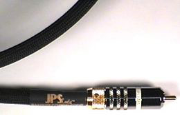 The Superconductor interconnects ($295 USD per pair)
use a thick, solid copper shield that not only provides a very low resistive return path
but a very low transfer impedance as well that continues to drop in magnitude with
increasing frequency in exactly the frequency range where it is most critical to do so,
unlike the more common braided shield constructions found in other cables. This makes its
use as an analog interconnect much more useful in reducing the effects of coupled RF in
conjunction with equipment that may not be designed to deal adequately with it. This is a
rather gross oversimplification of the problem, after all the aperture coupling effects at
the RCA connectors and the RF-current paths through and across the surfaces of the
equipment wasn't discussed, so we'll leave it at that for the moment as some are likely
wondering how the hell RF makes a difference in audio signal transfer anyway. Well,
there's that spectral contamination problem.
The Superconductor interconnects ($295 USD per pair)
use a thick, solid copper shield that not only provides a very low resistive return path
but a very low transfer impedance as well that continues to drop in magnitude with
increasing frequency in exactly the frequency range where it is most critical to do so,
unlike the more common braided shield constructions found in other cables. This makes its
use as an analog interconnect much more useful in reducing the effects of coupled RF in
conjunction with equipment that may not be designed to deal adequately with it. This is a
rather gross oversimplification of the problem, after all the aperture coupling effects at
the RCA connectors and the RF-current paths through and across the surfaces of the
equipment wasn't discussed, so we'll leave it at that for the moment as some are likely
wondering how the hell RF makes a difference in audio signal transfer anyway. Well,
there's that spectral contamination problem.