![[SoundStage!]](../sslogo3.gif) Max dB with Doug Blackburn Max dB with Doug BlackburnBack Issue Article |
| June 2000 WARNING: This installment of Maximum dB describes a component modification. Modifying any electronic device including, but not limited to, the DVD player described in the article can present serious fire, electric shock, and other safety hazards. In addition to damaging yourself, undertaking this type of DIY (do-it-yourself) project may result in permanent damage to your equipment and will likely void any applicable manufacturer’s warranties. As with all DIY articles featured in SoundStage!, the information presented is purely for the entertainment of the SoundStage! reader. SoundStage! does not suggest, recommend, or encourage any of its readers to modify their own equipment and can not and does not assume responsibility for incidental or consequential damage to equipment or injury to persons engaging in such modifications. In addition, SoundStage! can not and does not expressly or impliedly warrant or guarantee that the modifications described by dB in this article can be safely implemented or that such modifications will necessarily result in improved performance of the electronic device. Modifying a DVD/CD Transport or Player -- Part One By doing mods, you can really close the gap between high-priced and easily affordable digital sound. I’m going to cover a number of different kinds of modifications that could be performed on almost any moderate- to low-priced CD player, DVD player and even on low-cost DACs. I will be using the Pioneer DV-525 DVD player as the "example" in photos so you can see what the words are describing. But even though the Pioneer DV-525 is used in this article, many DVD players have similar parts and could benefit from similar modifications. The cost of these mods is low. Careful mods can raise the performance of a moderate-cost DVD player like the Pioneer DV-525 to such a degree that you will find the performance startling. As this is written, the street price of the Pioneer DV-525 is about $250. You should understand in advance that the Pioneer DV-525 is not a very good-sounding DVD player if you use the analog stereo outputs. Even after these mods, the sound from the analog outputs is pretty uninspiring. As a transport, though, the DV-525 is pretty amazing with these mods. The mods even improve the video image quality. Many, if not all, of these tweaks will apply to other mass-market DVD players, though locations of components may vary. However, this is not a DIY article with micro-detailed step-by-step instructions. If you aren’t already a DIY person, this article won’t help you become one. There are serious safety hazards if you attempt to open or modify audio components without disconnecting from AC power. Use all applicable safety rules for this project. SoundStage! and I assume no responsibility for accident, error or incorrect interpretation of this information which leads to the failure of your audio equipment or injury to you. If you are not a qualified technician, leave these modifications to people who are. We do not recommend that you perform them. Most manufacturers will void their new-product warranty if you perform these mods to their products. This is not that big of a deal if you are talking about a $250 DVD player. Use your own best judgment for your situation. In the interest of trying to keep this article shorter than a novella, I'm not going to delve into specific sonic benefits of each mod separately. As a group they improve transparency and detail, cause the music to come from a more silent background, and make the overall sound richer, more sophisticated and more refined. A kind of gray blanket over everything is removed, making the presentation more open and natural and giving a feeling of boundaries and limitations being removed. It takes a rather overbuilt and expensive product to exceed the performance of a Pioneer DV-525 with these mods -- or variations thereof. Each individual mod contributes a little or a lot in one direction or another. Let's get on with it then. Power cord upgrade This permits using commercial or DIY power cords which have IEC adapters on the component end. You can then compare different power cords and select the one that sounds best to you.
Remove the plastic power connector from the
power-supply PCB. This connector generally has two or three wires soldered to the circuit
board. De-solder those connections, and remove the connector. Using a chassis nibbler (shown right, about $11 at Radio Shack), open the existing power cord hole on the back panel to accept a 20-amp IEC connector (20-amp IEC connectors sound better than the 15-amp connectors). Install the 20-amp IEC adapter using small brass screws, flat washers and nuts (sounds better than steel hardware). You will have to drill two holes in the chassis for the mounting screws.
When you install the 20-amp IEC connector, install it from the outside to cover up the edges of the enlarged hole you made. This means you don't have to take a lot of time making the enlarged hole look pretty. Just nibble out a rough shape. When you install the IEC from the outside, it will cover the rough appearance of the hole. Bridge diode replacement
Replace these diodes with diodes rated at least 200 volts and 1 amp. Digikey (www.digikey.com) is a good source for cheap parts that work well. There are three types of replacements that will make a sonic improvement: small HEXFREDs, soft-recovery-type diodes (all General Instrument diodes are this type; thanks to Mike VansEvers for the tip -- the theory with these diodes is that they turn off so gradually that they do not emit the little spurt of noise during switching that other diodes emit), ultra-fast recovery (50ps or lower). Don't ask me which sound the best. Theoretically the soft recovery or HEXFREDs should sound the best. When installing the replacements, observe correct polarity of the replacement diodes. Diodes have a line on one end of their body; the line-end of the diode should match with a circuit-board hole with a white circle around it or a line with a triangle point touching the line. Don’t install the diodes incorrectly or you could see smoke at power-up. Add film-and-foil power-supply bypass filter capacitor Locate the large 200-volt electrolytic capacitor
at the left edge of the power supply PCB, toward the rear of the PCB. See the black
cylinder standing up on the circuit board at the lower center of the image above. Flip the power-supply PCB over and locate the solder pads where the connections for that electrolytic capacitor are and what nearby unused holes connect to the same solder pads but in different locations. The two photos show the added capacitor (white) from both sides. In the right photo, the capacitor lead is shown in lime green for clarity. This capacitor happens to be a 2uF InfiniCap made by Wonder/TRT. Its leads are not epoxied on the ends, making it possible to pop a lead right off the capacitor if you are too rough with it. Normal handling should not cause a problem, though.
Replace existing electrolytic filter capacitor? Most CD players and transports will sound even better if you replace the stock electrolytic filter cap(s) with better-quality caps. Panasonic HFQ caps are a good choice for this application and are available at reasonable cost from Digikey. You should read the values off of the existing capacitor. You can safely double the capacitance and keep the operating voltage equal or higher than the original equipment filter(s). If you happen to have Nippon Chemicon PL or Black Gate PK series electrolytics already, they are also good choices for this application. ...to be continued next month with chassis and transport dampening, and much more. ...Doug Blackburn
|
|
| All Contents Copyright © 2000 SoundStage! All Rights Reserved |
 Remove the stock power cord.
Most often you will have to squeeze the power cord strain relief with a pair of pliers
before it will push out of the chassis. Most strain reliefs have a "key" in one
side that expands to fill the chassis hole so the strain relief cannot come out of the
chassis hole. Squeeze the pliers down on that key to compress it so the strain relief can
be removed.
Remove the stock power cord.
Most often you will have to squeeze the power cord strain relief with a pair of pliers
before it will push out of the chassis. Most strain reliefs have a "key" in one
side that expands to fill the chassis hole so the strain relief cannot come out of the
chassis hole. Squeeze the pliers down on that key to compress it so the strain relief can
be removed.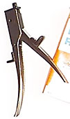 Clean the solder out of the
circuit-board holes to facilitate installation of the new wires.
Clean the solder out of the
circuit-board holes to facilitate installation of the new wires.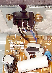 Use good-quality 18-gauge wire
(Teflon-insulated copper, for example) to connect the IEC socket to the power-supply PCB.
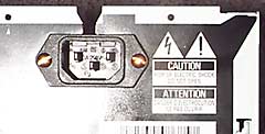
Install the IEC socket with the center (ground) pin down (closest to the shelf/table) and
run the wires straight down from the left IEC terminal to the left PCB power connection
and right IEC terminal to right PCB connection -- this gives you correct power polarity
for the Pioneer DV-525. Connect the center ground terminal from the IEC to the metal
chassis of the DV-525 using any screw that provides a tight grip on the ground wire. In
the photo, a second brass nut and washer on the right screw secure the ground wire to
chassis ground.
Use good-quality 18-gauge wire
(Teflon-insulated copper, for example) to connect the IEC socket to the power-supply PCB.
Install the IEC socket with the center (ground) pin down (closest to the shelf/table) and
run the wires straight down from the left IEC terminal to the left PCB power connection
and right IEC terminal to right PCB connection -- this gives you correct power polarity
for the Pioneer DV-525. Connect the center ground terminal from the IEC to the metal
chassis of the DV-525 using any screw that provides a tight grip on the ground wire. In
the photo, a second brass nut and washer on the right screw secure the ground wire to
chassis ground.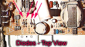 Locate the four small
bridge-rectifier diodes at the left-rear corner of the power supply PCB. Remove all of
them. Note: Replacement diodes are shown in photo; original diodes are black and
cylindrical.
Locate the four small
bridge-rectifier diodes at the left-rear corner of the power supply PCB. Remove all of
them. Note: Replacement diodes are shown in photo; original diodes are black and
cylindrical.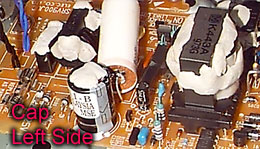 Also visible in the image below, just
left of center at the bottom. The large white capacitor, top center, is the added
film-and-foil filter capacitor.
Also visible in the image below, just
left of center at the bottom. The large white capacitor, top center, is the added
film-and-foil filter capacitor.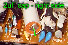 When you have found
one unused hole on each "side" of the electrolytic capacitor, solder your new
film-and-foil cap -- 2uF, 400V or higher for 120 VAC, 1uF, 600 V for 240V operation.
Install the new capacitor so that it parallels the existing electrolytic. On my DV-525
there was an unused hole for a component that was not installed and a through hole for a
heat sink that was not installed. If you are feeling really tweaky, you can parallel a
.01uF film-and-foil with the other two caps too. Any good quality film-and-foil cap will
be fine here, but watch the voltage rating… only 400 V or higher and a cap rated for
AC voltage would be best, though you are unlikely to have trouble with a cap rated for 400
VDC.
When you have found
one unused hole on each "side" of the electrolytic capacitor, solder your new
film-and-foil cap -- 2uF, 400V or higher for 120 VAC, 1uF, 600 V for 240V operation.
Install the new capacitor so that it parallels the existing electrolytic. On my DV-525
there was an unused hole for a component that was not installed and a through hole for a
heat sink that was not installed. If you are feeling really tweaky, you can parallel a
.01uF film-and-foil with the other two caps too. Any good quality film-and-foil cap will
be fine here, but watch the voltage rating… only 400 V or higher and a cap rated for
AC voltage would be best, though you are unlikely to have trouble with a cap rated for 400
VDC.